 English
 简体中文
简体中文
 ru
ru
 es
es

How to Measure Solenoid Valve Coil Resistance with a Multimeter
A solenoid valve coil can fail even when the valve itself is mechanically functional. One of the quickest ways to check the electrical condition of a solenoid valve coil is to measure its resistance with a digital multimeter.
For excavators, skid steer loaders, backhoe loaders and other hydraulic equipment, an abnormal resistance reading may indicate an open circuit, shorted winding, damaged coil or an incorrect replacement coil. If a replacement is needed, explore our solenoid valve coils for excavators, skid steer loaders and other hydraulic equipment.
This guide explains how to measure solenoid valve coil resistance with a multimeter, how to interpret the reading, and what to check when the measured resistance is outside the expected range.

What Is Solenoid Valve Coil Resistance?
Solenoid valve coil resistance is the electrical resistance of the winding inside the coil. It is measured in ohms (Ω) using a multimeter.
When the correct voltage is applied to the coil, electrical current flows through the winding and generates a magnetic field. This magnetic field activates the solenoid valve.
The relationship between voltage, current and resistance can be described by Ohm’s law:
I = V / R
Where:
- I = current in amperes (A)
- V = voltage in volts (V)
- R = resistance in ohms (Ω)
Because coil design, voltage, power rating and winding characteristics vary between manufacturers and applications, there is no single resistance value that applies to every solenoid valve coil.
For this reason, the measured value should always be compared with the specification for the exact coil or part number whenever possible.
What You Need to Measure Solenoid Coil Resistance
You only need a few basic tools:
- Digital multimeter
- Solenoid valve coil
- Equipment service manual or coil specification
- Basic hand tools, if the coil needs to be removed
- Safety gloves and appropriate personal protective equipment
Before testing, make sure you know the rated voltage and, if available, the specified resistance of the coil.
How to Measure Solenoid Valve Coil Resistance
Follow these steps to measure the resistance of a typical two-terminal solenoid valve coil.
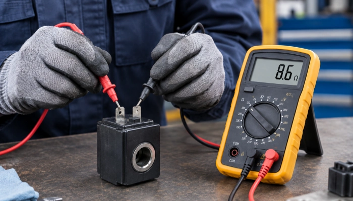
Measuring solenoid valve coil resistance with a digital multimeter.
Step 1: Turn Off the Equipment
Before testing, shut down the excavator, skid steer loader or other hydraulic equipment.
Remove the ignition key and follow the equipment manufacturer’s safety procedures.
Do not measure coil resistance while the coil is being electrically energized.
The purpose of a resistance test is to measure the winding itself, not the powered control circuit.
Step 2: Disconnect the Solenoid Coil
Disconnect the electrical connector from the solenoid valve coil.
If the coil is connected to a wiring harness or controller, make sure the coil is electrically isolated before measuring resistance.
This is important because measuring resistance through the connected circuit can produce an incorrect reading and may potentially damage the multimeter or electronic control components.
Step 3: Set the Multimeter to Resistance Mode
Turn the digital multimeter to the resistance setting marked with the Ω symbol.
If the multimeter uses automatic ranging, simply select the resistance function.
If it uses manual ranging, choose an appropriate resistance range based on the expected specification of the coil.
Step 4: Check the Multimeter Before Testing
Touch the two multimeter probes together.
The meter should normally show a value close to zero ohms, although a small amount of resistance from the test leads themselves is normal.
This quick check confirms that the meter and test leads are functioning properly.
Step 5: Place the Probes on the Coil Terminals
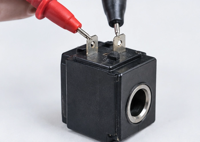
Place one multimeter probe on each terminal of the solenoid valve coil.
For a typical two-terminal solenoid valve coil:
- Place one probe on the first electrical terminal.
- Place the other probe on the second terminal.
- Wait for the reading to stabilize.
- Record the resistance shown on the multimeter.
For example, the multimeter may display:
8.6 Ω
The actual value is not important by itself. The next step is to compare it with the manufacturer’s specified resistance for that particular coil.
How to Interpret Solenoid Coil Resistance Readings
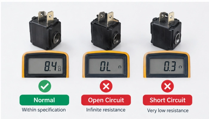
Examples of normal, open-circuit and low-resistance solenoid coil readings.
A resistance measurement can provide useful information about the electrical condition of a solenoid coil.
| Multimeter Reading | Possible Condition | What It May Indicate |
|---|---|---|
| Within manufacturer’s specification | Normal electrical continuity | Coil winding is likely electrically intact |
| OL / ∞ | Open circuit | Broken winding or internal connection |
| Very low resistance | Possible short circuit | Damaged or shorted winding |
| Higher than specification | Abnormal | Possible winding damage or connection problem |
| Lower than specification | Abnormal | Possible shorted winding or incorrect coil |
These results should be treated as diagnostic indicators rather than automatic proof of failure.
What Does OL Mean When Testing a Solenoid Coil?
If the multimeter displays OL, infinity or another indication of an open circuit, the electrical path through the coil is interrupted.
A common cause is a broken winding inside the coil.
However, poor probe contact, damaged terminals or a faulty connector can also cause an apparent open circuit.
Check the terminals and connections before replacing the coil.
What Does Very Low Resistance Mean?
A resistance reading that is significantly lower than the specified value may indicate a shorted winding.
However, do not automatically assume that any low resistance reading means the coil has failed.
Compare the measurement with the manufacturer’s specification for the exact coil.
What Does High Resistance Mean?
If the measured resistance is significantly higher than the specified value, the coil may have a damaged winding or a poor electrical connection.
Corrosion or contamination around the terminals can also affect the measurement.
What Resistance Should a Solenoid Valve Coil Have?
There is no universal resistance value for solenoid valve coils.
The correct resistance depends on several factors, including:
- Rated voltage
- Coil power
- Winding design
- Manufacturer
- Solenoid valve design
- Operating temperature
- Specific part number
For example, two coils designed for the same type of hydraulic application may have different resistance values because their electrical specifications are different.
Therefore, a resistance value should not be judged as “good” or “bad” simply because it falls within a commonly quoted range online.
The most reliable approach is to compare the measurement with the specification for the exact coil.
For a quick reference, see our Solenoid Valve Coil Voltage & Resistance Chart.
12V vs. 24V Solenoid Valve Coil Resistance
12V and 24V solenoid valve coils are commonly used in mobile hydraulic equipment.
However, voltage alone does not determine the exact resistance of a coil.
For a coil with a given power rating, electrical relationships can be expressed as:
P = V² / R
Where:
- P = electrical power
- V = voltage
- R = resistance
This means that coil resistance is related to both voltage and power.
A 24V coil cannot simply be substituted for a 12V coil because the physical appearance may be similar. The voltage rating, resistance, power consumption and valve compatibility all need to be confirmed.
Similarly, do not assume that two coils with the same voltage rating are interchangeable.
Always verify the correct part number and electrical specifications before installing a replacement coil.
Can a Solenoid Coil Have Normal Resistance and Still Be Bad?
Yes.
A resistance test is an important first diagnostic step, but it does not prove that a solenoid coil is completely functional.
A coil may show a normal resistance reading while still having another problem, such as:
- Insulation breakdown
- Intermittent internal connection
- Damage that appears only when the coil becomes hot
- Connector damage
- Incorrect operating voltage
- Internal winding deterioration
If the resistance is within specification but the solenoid valve does not operate, continue troubleshooting the electrical circuit and the valve itself.
Check the power supply, wiring harness, connector, control signal and valve condition.
Common Problems When Measuring Solenoid Coil Resistance
1. The Multimeter Shows OL
Possible causes include:
- Open winding
- Broken internal connection
- Poor probe contact
- Damaged electrical terminal
- Connector problem
First check the probe contact and terminals. If the coil still shows an open circuit, the winding may be damaged.
2. The Reading Changes Constantly
An unstable reading may be caused by:
- Loose electrical terminals
- Corrosion
- Poor probe contact
- Damaged connector
- Intermittent winding connection
Make sure the probes are firmly contacting clean terminals and repeat the measurement.
3. The Resistance Is Much Higher Than Expected
Possible causes include:
- Damaged winding
- Poor connection
- Corroded terminals
- Incorrect coil
Compare the result with the specification for the exact part number.
4. The Resistance Is Much Lower Than Expected
Possible causes include:
- Shorted winding
- Internal coil damage
- Incorrect replacement coil
- Measurement error
Do not replace the coil based on a generic resistance chart alone. Verify the manufacturer’s specification.
5. The Coil Has Normal Resistance but the Valve Does Not Work
If the resistance is normal, investigate the rest of the system.
Check:
- Supply voltage
- Wiring harness
- Electrical connector
- Ground connection
- Controller or ECU output
- Hydraulic valve
- Mechanical components
A normal resistance measurement only confirms that the winding has electrical continuity within the measured conditions.
How to Test a Solenoid Valve Coil on an Excavator
On an excavator, the solenoid valve coil is normally connected to the machine’s electrical control system through a wiring harness.
A practical troubleshooting sequence is:
Solenoid valve fault
↓
Inspect the coil and connector
↓
Disconnect the coil
↓
Measure coil resistance
↓
Compare the reading with the correct specification
↓
Resistance abnormal → investigate or replace the coil
Resistance normal → check voltage, wiring and control signals
This approach can help prevent unnecessary replacement of the complete solenoid valve when only the coil is electrically defective.
When Should You Replace a Solenoid Valve Coil?
A solenoid valve coil may need replacement when:
- The winding is open.
- Resistance is significantly outside the manufacturer’s specification.
- The coil has visible physical damage.
- The coil shows signs of severe overheating.
- The electrical connector or terminals are damaged.
- The coil repeatedly fails during normal operation.
- The coil is confirmed to be incompatible with the equipment or valve.
If the valve body is mechanically functional, replacing only the solenoid coil may be a more practical solution than replacing the complete valve.
Before ordering a replacement coil, confirm the:
- Part number
- Rated voltage
- Resistance
- Connector type
- Coil dimensions
- Valve compatibility
Solenoid Valve Coil Resistance Test: Quick Checklist
Use this checklist when diagnosing a hydraulic solenoid coil:
1. Shut down the machine
Make sure the equipment is safely powered off.
2. Disconnect the coil
Isolate the coil from the wiring harness and control circuit.
3. Set the multimeter to Ω
Use the correct resistance range.
4. Check the meter
Touch the probes together to verify the test leads.
5. Measure the coil
Place one probe on each terminal.
6. Record the resistance
Write down the measured value.
7. Compare it with the correct specification
Do not rely only on a generic resistance value.
8. Continue troubleshooting if necessary
A normal resistance reading does not eliminate wiring, voltage, control or hydraulic problems.
Need a Replacement Solenoid Valve Coil?
If your solenoid valve coil has been diagnosed as electrically faulty, replacing the coil may be sufficient when the valve body remains in good condition.
We supply replacement hydraulic solenoid valve coils for excavators, skid steer loaders and other construction equipment.
When selecting a replacement coil, always confirm the part number, voltage, resistance, connector type, dimensions and valve compatibility.
If you are unsure which solenoid valve coil you need, contact us with the original part number, coil photos or equipment information so the correct replacement can be identified.
Frequently Asked Questions
What resistance should a solenoid valve coil have?
There is no single resistance value for all solenoid valve coils. The correct resistance depends on the coil’s voltage, power rating, winding design and specific part number. Always compare the measurement with the manufacturer’s specification.
How do I test a solenoid valve coil with a multimeter?
Disconnect the coil from the electrical circuit, set the multimeter to resistance mode (Ω), place one probe on each coil terminal and compare the measured resistance with the correct specification.
What does OL mean on a solenoid coil test?
OL usually indicates an open circuit, meaning the multimeter cannot detect a continuous electrical path through the coil. Check the terminals and probe contact before concluding that the winding has failed.
Can I test a solenoid coil without removing it from the valve?
Yes. In many cases, resistance can be measured while the coil remains installed on the valve. However, the electrical connector should be disconnected so that the measurement is taken across the coil itself rather than through the control circuit.
Can a solenoid coil have the correct resistance and still be defective?
Yes. Resistance testing checks electrical continuity under the test conditions, but it cannot identify every possible coil, connector, wiring or operating-temperature problem. Further testing may be required if the valve still does not operate correctly.
